
2d model ball mill manufacturer Grasping strong production capability, advanced research strength and excellent service, Shanghai 2d model ball mill supplier create the value and bring values to all of customers.
 WhatsApp)
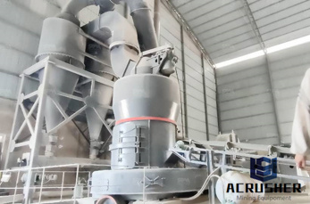
3d model of ball mill trunnion bearing supremewheels3d model of ball mill trunnion bearing. Horizontal grinding mills SKF. SKF trunnion support housings. Two robust, double Vring seals keep lubricants in and Elimin
Nov 21, 2008· Re: Ball End Mill Sweep The shape a ball end mill leaves in material at the corners depends on how the tool path is programmed, in JD's example the cutter is rolled around the corners, how the exact toolpath will be generated varies depending on the machine tool and whether cutter compensation is used or not.
3d model drawing ball mill. Timken Ball Housed Unit Catalog ball mill model cadA1 TIMKEN HOUSED UNIT CATALOG Download 3D Models and 2D Drawings at cadtimken 1 Use Timken spherical roller bearing solidblock housed units in metals mills aggregate and cement mining power generationCADCAM Technology for 3 Axis CNC Mill
The ball mill simulation with 1.25 million spheres is completed in 27 hours. In the near future, these compute times can be halved with the advances in graphic card hardware. ... At the outset it is useful to discuss the merits of 3D code in comparison with 2D code. The 2D code is ... within the mill. At each contact a collision model is used ...
Solid Carbide 2D/3D Carving Tapered and Straight Ball Nose (Conical Ball) & Tapered and Straight Flat Bottom (End Mill), ZrN Coated CNC Router Bit Collection. Priced From . ... Perfect for model-makers on large 3D milling profiles in abrasive EPS and other materials;
2D Model for Ball Mills. By F. Campo and J. bar. Abstract. Abstract: This work develops a mathematical model that explains the ball mills operational speed. The scope of the model is defined by the powder as the number of particles per cm 3 and the Relevance defined as the ratio between different forces. In this study, the Relevance is ...
May 08, 2015· Great Wall ball grinding mill process ball grinding mill working principle 3D our website:, our email:sales@gw...
Jan 16, 2014· Using the Herz-Mindlin model, seen in the sun wheel reference frame. 108 steel balls. Skip navigation ... 2D planetary ball mill simulation b. Loading... Unsubscribe from b?
Feb 20, 2018· A 1/32 straight ball nose bit will probably break. I 1/4" shank 1/32 ball nose tapered bit is VERY STRONG MOST of the time, the 3D surface needs only the very tip of the ball nose - so all the stuff behind the tip (the taper part) doesn't really matter.

HQMaster CNC Router Bit 1/8" Shank Ball Nose End Mill 2mm Cutting Dia. 2-Flute Spiral Upcut Milling Cutter Engraving Carving Tool Set Tungsten Steel 17mm CEL, .

4pcs/Package Assorted CNC 2D and 3D Carving R0.25 & R0.5 & R0.75 & R1.0 with 1/8" (3.175mm) Shank Tungsten Solid Carbide Tapered Ball Nose End Mills and Cone Cutter HRC55 with Coated: Amazon: Industrial & Scientific
Jun 06, 2014· What is the best way to model a ball end mill feature? i know there must be many ways, what method do you use on flat surface. complex surface, and cylinder?? on top i used a simple 2D extrude cut with fillet on bottom, lower i used a swert cut-but not sure how to get the rounded start and end conditions ???
There are two ways to use the Inventor HSM chamfering feature depending on whether the CAD model already has chamfered features or not. CAD model with no chamfer CAD model with chamfer feature In both cases, you can use the 2D Contour strategy to chamfer the model. First, define and select a chamfer mill tool. This automatically enables the Chamfer option in the 2D Contour parameter group ...
A craze for shock produced the 2D Ball Mill. After all the sample changes to the paste form and makes the blunder. The 3D Ball, the craze for milling almost succeeded by non-outbreak. For 2D, – Rotation axis: 600rpm, – Revolution: 1,500 rpm – Total load electric current: 2.5A – Temperature. 42℃ (Room Temperature 23℃)
ball mill for ore ginding. The Computer-Aided Design ("CAD") files and all associated content posted to this website are created, uploaded, managed and owned by third party users.
Portable Ball Mill Turnion Lathe 3D CAD model GrabCAD. May 11, 2015 This is portable lathe for machining worn diameters on operationally damaged ball mill trunnions up to 2m diameter and 900mm axial length, w. Autogenous mills, semiautogenous mills and ball mills for Polysius.

Jun 14, 2018· That was my comment that an end-mill wasn't the plan but was close enough to show the concept. A radiused cutter was the plan but the end-mill caused enough pain to model in. A ball-nose cutter would require a lot more cuts than the single U shaped path. This model was just an example to illustrate the difficulties in modelling cutter paths.
Inventor CAM supports chamfering with ball end mills and bull end mills. This may be useful in cases where you are already using a ball or bull end mill in a part and wish to chamfer off sharp edges, but save a tool change to an ordinary chamfering tool. With small chamfer sizes, the differences between a flat chamfer using a chamfering tool and a slightly rounded chamfer may be negligible
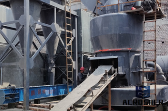
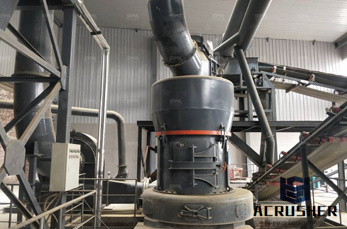
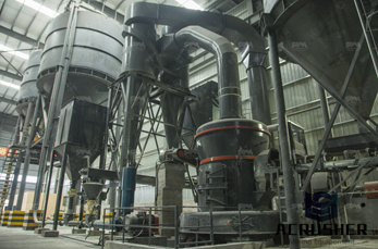
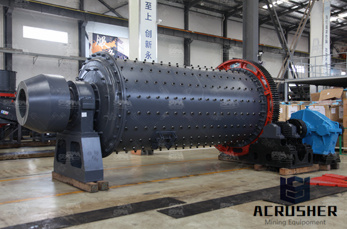
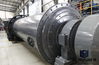
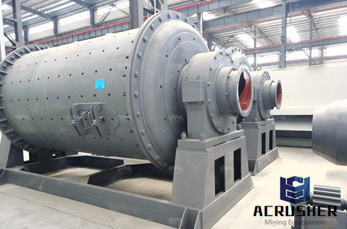
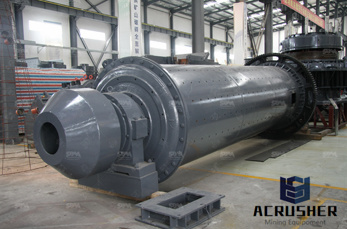
A ball mill is a type of grinder used to grind, blend and sometimes for mixing of materials for use in mineral dressing processes, paints, pyrotechnics, ceramics and selective laser sintering. It works on the principle of impact and attrition: size reduction is done by impact as .
Jul 15, 2016· How to Use Autodesk Fusion 360 for CNC Milling. ... parallel, 2D contour, etc.) to clear the excess material. For each of these operations, the proper tool (bull nose mill, ball end mill, chamfer mill, ... to the use of tabs — which keep your model in place until you manually saw it out, rather than it being carved loose and compromising its ...
Ball Nose (Conical Ball) Solid Carbide Spiral CNC 2D/3D Carving Tapered and Straight ZrN Coated Router Bits, In-Stock & Ready to Ship Today! Large Selection of ZrN Coated Router Bits.
7 – Radius Milling . Radius milling uses a 2D Contour-like toolpath to produce an external fillet. Using the 2D toolpath requires a Radius Mill, but you can accomplish similar results with a Ball Mill and 3D contour toolpath. 8 – Spot Drilling . You can use center drilling to create a .
I've been trying to model cut produced by a ball end mill taking an arbitrary 3D path. I know how to do this for 2D paths (and this has been discussed a couple of times on this forum), but I have had little to no success extending this to paths in 3D. I've attached an Inventor file that demonstrates ...

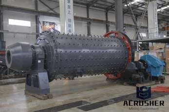
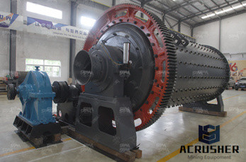
the mill is used primarily to lift the load (medium and charge). Additional power is required to keep the mill rotating. 8.1.3 Power drawn by ball, semi-autogenous and autogenous mills A simplified picture of the mill load is shown in Figure 8.3 Ad this can be used to establish the essential features of a model for mill .
WhatsApp)