
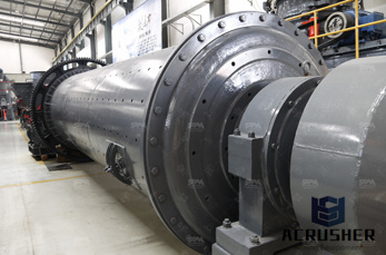
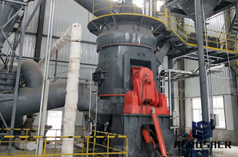
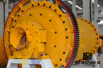
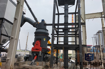
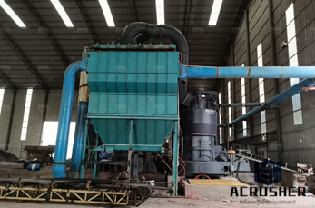
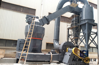
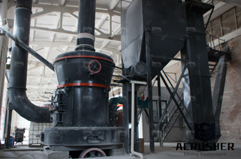
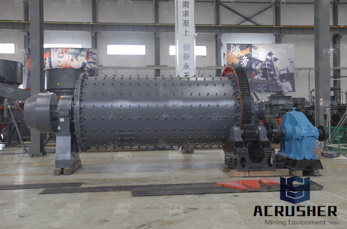
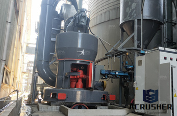
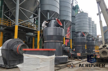
flow diagram for coal preparation plant manufacturer Grasping strong production capability, advanced research strength and excellent service, Shanghai flow diagram for coal preparation plant supplier create the value and bring values to all of customers.
 WhatsApp)
Off-sites, and Unit 700—Hydrogen Plant. A simplified block flow diagram (Figure 2-1) and accompanying description is provided below. Figure 2-1: DCL Facility—Simplified Block Flow Diagram In Unit 100—Coal Preparation, the coal is received via rail, barge, and truck, stockpiled, crushed, and dried, and stored in silos before being ...
Aug 07, 2016· Process Description and flow diagram of Coal Based DRI Plant Process Description and flow diagram of Coal Based DRI Plant. Description of Sponge Iron Manufacturing Process . Most of the plants in India use DRI process—a solid state direct reduction process by which iron ore is reduced to sponge without phase change.
The scheme used in physical coal cleaning processes varies among coal cleaning plants but can generally be divided into four basic phases: initial preparation, fine coal processing, coarse coal processing, and final preparation. A process flow diagram for a typical coal cleaning plant is presented in Figure 11.10-1.
oven battery. Flow diagrams are provided in Figures 12.2-2 and -3 to give an overview of the process from coal preparation to byproduct recovery. These operations will be discussed in greater detail for the three major subprocesses: coal preparation and charging, thermal distillation and pushing, and byproduct recovery.
A flow diagram of a 400 ton per hour coal plant that produces both metallurgical coal and steam coal for power generation. Generally speaking, metallurgical coal is cleaner, has higher carbon content and is easier to process than the lower rank steam coals. At this prep plant, all feed coal (ROM) is crushed to -2" before entering the plant ...

Thermal-based power plants can produce electricity from coal or other fuel sources. The coal-fired process requires three different steps to turn energy released from burning coal to generating electricity for consumption. Coal fired power plants, while producing power, require a lot of water and produce a lot of pollutants like ash and CO2.
Peabody Wester n Coal Company . December 18, 2017 . Gerardo Rios Air Pe1mits Manager Air Division (Attn: AIR-3) USEP A Region 9 ... Process Flow Diagram - Kayenta Preparation Plant .....6 - with location of each spray system and its number of spray nozzles Figure 2. Underground Hopper ...
Coal Handling Plant – Process Flow Diagram – Raw Coal Handling New ROM Bin CV-104 Raw Coal Conveyor New Sizing ... Coal Preparation Plant – Other Process Considerations Field modify existing ... ACPS New South Wales February Meeting February 15, 2012 – New South Wales, Australia. Title:
The Loveridge facility produces coal from the mine and transports the coal by conveyor belts to the preparation plant before shipment. The Loveridge facility is an active bituminous coal underground mine covered under Standard Industrial Classification (SIC) Code 1222. The facility has the potential to operate 24 hours per day, 7 days per week.
financially appealing. Since coal is more energy dense and the resource is more geospatially concentrated relative to biomass, coal transport can be economical over greater distances. Thus, most coal power plants are at least an order of magnitude larger than biomass power plants. Coal power plants can scale more easily, resulting in reduced
Coal preparation plant . A coal preparation plant is a facility that washes coal of soil and rock, .... stream, ultimately reverses its vertical velocity direction and flows upward to the cyclone over flow .
A process flow diagram (PFD) is a diagram commonly used in chemical and process engineering to indicate the general flow of plant processes and equipment. The PFD displays the relationship between major equipment of a plant facility and does not show minor .
A brief description of the various processing plants within an integrated gasification combined cycle (IGCC complex) is given below in reference to the block flow diagram (Figure 2) discussed under Typical IGCC Configuration. A more detailed discussion of each of the processing plant functions is available; links are embedded in the following discussion.
Figure 1: A Simplified Coal-to-SNG Block Flow Diagram. The economic viability of producing synthetic natural gas (SNG) through coal gasification is heavily dependent on the market prices of natural gas and the coal feedstock to be used, in addition to the capital cost of the gasification plant.
Coal Preparation Plant Flow Diagram Auto Electrical Wiring Diagram #23120500573 – Coal Washing Process Flow Chart, with 33 More files. Free Flowchart Templates MySullys. Home › Coal Washing Process Flow Chart › Gallery.
Energy Balance of a Coal-Fired Power Plant in Condensing Operation . DOSA ION, ... average operating efficiency of U.S. coal plants is about 31.8 %, and the costs and implications of ... The 210 MW power plant unit schematic diagrams is presented in Fig. 1. The unit consists of a steam turbine with reheating, steam, generator ...
A coal preparation plant is a facility that washes coal of soil and rock, crushes it into graded .... Measurement of flow, density, levels, ash and moisture are inputs to the control system. ... processing, and final preparation. A process flow diagram for a typical coal cleaning plant is presented in Figure 11.10-1. In the initial preparation ...
Description of a natural-gas processing plant. There are a great many ways in which to configure the various unit processes used in the processing of raw natural gas. The block flow diagram below is a generalized, typical configuration for the processing of raw natural gas from non-associated gas wells. It shows how raw natural gas is processed ...
Flexibilization of coal-fired power plants ... coal-fired power plant. This process flow diagram illustrates the three turbine groups (high, intermediate ... 1. Coal preparation and distribution 2. Flue gas path 3. Heating surfaces (walls and tube bundles) 4. Water flowing through the steam generator
A flow diagram of a 400 ton per hour coal plant that produces both metallurgical coal and steam coal for power generation. Generally speaking, metallurgical coal is cleaner, has higher carbon content and is easier to process than the lower rank steam coals. At this prep plant, all feed coal (ROM) is crushed to -2" before entering the plant ...
The facility is designated as preparation plant No. 1. The clean coal from this plant is sent directly to a large steam electric power plant. Aschematic flow diagram of coal preparation plant No. 1 is shown in Figure 1. Preparation plant No. 1 isa450Mg/h (500 t/h) coal washing plant.

Coal Handling Plant – Process Flow Diagram – Raw Coal Handling New ROM Bin CV-104 Raw Coal Conveyor New Sizing ... Coal Preparation Plant – Other Process Considerations Field modify existing ... ACPS New South Wales February Meeting February 15, 2012 – New South Wales, Australia. Title:
Flow diagram - Wikimedia Commons. A process flow diagram (PFD) is a diagram commonly used in chemical and process...Electrical energy distribution in a coal fired power plant
Jun 16, 2014· Turbine and its auxiliaries 4. Condenser and Cooling Tower 5. Ash Handling Plant 6. Electrical Equipments Major Components of Coal Based Thermal Power Plants Major Components of Coal Based Thermal Power Plants 8. Steam Flow DiagramSteam Flow Diagram 9. Coal to ElectricityCoal to Electricity 10. • A coal handling plant is the area of the ...
WhatsApp)